HDLBits刷题日记(五)
打算利用碎片化时间重温一遍Verilog语法,好记忆不如烂笔头,在此记录一下HDLBits刷题的过程,记录一些知识点,方便日后再次复习。
1、Verilog Language - Modules:Hierarchy
Problem 19 : Module
模块,它是一个通过输入和输出端口与外部进行交互的电路。更大、更复杂的电路是通过将较小的模块组合成较大的模块,以及将其他部分 (如 assign 语句和 always 块) 连接在一起来构建的。这形成了一个层次结构,因为模块可以包含其他模块的实例。模块的层次结构是通过在另一个模块中实例化一个模块来创建的,只要所有使用的模块都属于同一个项目 (这样编译器就知道在哪里找到该模块)。通常一个文件只包含一个模块。
在实例化模块时,有两种常用的方式来进行模块端口的信号连接:按端口顺序以及按端口名称连接端口。
按端口顺序, mod_a instance1 ( wa, wb, wc ); wa, wb, wc 分别连接到模块的 第一个端口(in1),第二个端口(in2)以及第三个端口(out)。这里所谓的端口顺序指的是模块端口的定义顺序。这种方式的弊端在于,一旦端口列表发生改变,所有模块实例化中的端口连接都需要改变。
按端口名称, mod_a instance2 ( .out(wc), .in1(wa), .in2(wb) ); 在这种方式中根据端口名称指定外部信号的连接。这样一来就和端口声明的顺序完全没有关系。一旦模块出现改动,只要修改相应的部分即可。实际上,一般都使用这种方式来进行模块实例化。
下图显示了一个非常简单的电路,其中包含一个子模块。在这个练习中,创建一个模块 mod_a 的实例,然后将模块的三个引脚 (in1、in2 和 out) 连接到顶级模块的三个端口 (线路 a、b 和 out)。
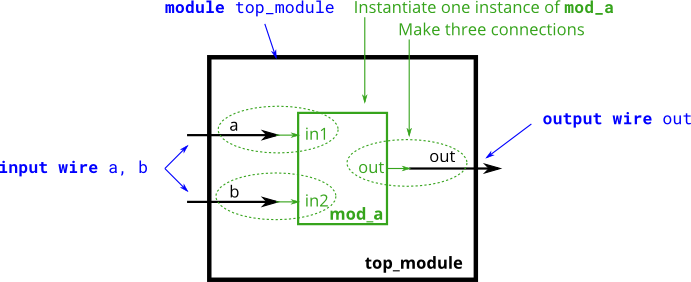
module top_module ( input a, input b, output out );
        mod_a U_mod_a (
        .in1(a),
        .in2(b),
        .out(out)
        );
    //mod_a U_mod_a(a, b, out); //使用按照端口顺序的方式 声明信号连接
endmodule
Problem 20 : Module pos
module mod_a ( output, output, input, input, input, input );
模块 mod_a 有四个输入端口和两个输出端口。它的端口声明顺序是:out1、out2、in1、in2、in3、in4。现在在顶级模块中实例化 mod_a 模块,并将其端口连接到顶级模块的四个输入端口 (a、b、c 和 d) 和两个输出端口 (out1 和 out2)。注意,端口连接的顺序与模块的端口声明顺序相同。
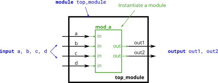
module top_module (
    input a,
    input b,
    input c,
    input d,
    output out1,
    output out2
);

    mod_a name(out1,out2,a,b,c,d);

endmodule
Problem 21 : Module name
module mod_a ( output out1, output out2, input in1, input in2, input in3, input in4);
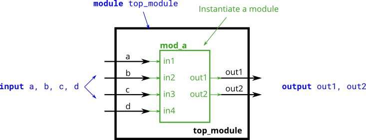
module top_module (
    input a,
    input b,
    input c,
    input d,
    output out1,
    output out2
);

    mod_a name(.out1(out1),.out2(out2),.in1(a),.in2(b),.in3(c),.in4(d));

endmodule
Problem 22 : Module shift
给出了一个名为 my_dff 的模块,包含两个输入和一个输出(实现 D 触发器的功能)。实例化三个 my_dff,然后将它们连接在一起,构成长度为 3 的移位寄存器。注意:clk 端口需要连接到所有的寄存器实例上。
module my_dff ( input clk, input d, output q );
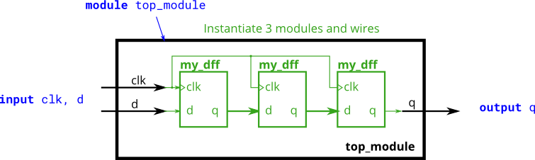
module top_module (
    input clk,
    input d,
    output q
);

    wire q1, q2; //定义中间信号

    my_dff dff1(clk, d, q1); //实例化第一个 D 触发器
    my_dff dff2(clk, q1, q2); //实例化第二个 D 触发器
    my_dff dff3(clk, q2, q); //实例化第三个 D 触发器

endmodule
Problem 23 : Module shift8
module my_dff8 ( input clk, input [7:0] d, output [7:0] q );
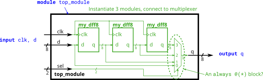
module top_module (
    input clk,
    input [7:0] d,
    input [1:0] sel,
    output [7:0] q
);
    wire [7:0] q1, q2,q3; //定义中间信号

    my_dff8 dff1(clk, d, q1); //实例化第一个 D 触发器
    my_dff8 dff2(clk, q1, q2); //实例化第二个 D 触发器
    my_dff8 dff3(clk, q2, q3); //实例化第二个 D 触发器

    assign q = (sel == 2'b00) ? d : //当 sel 为 00 时,输出 d
               (sel == 2'b01) ? q1 : //当 sel 为 01 时,输出 q1
               (sel == 2'b10) ? q2 : //当 sel 为 10 时,输出 q2
               q3; //当 sel 为 11 时,输出 q3

    // always @(*)  // 组合逻辑always块
    // case(sel)
    //   2'h0: q = d;
    //   2'h1: q = q1;
    //   2'h2: q = q2;
    //   2'h3: q = q3;
    // endcase

endmodule
Problem 24 : Module add
module add16 ( input[15:0] a, input[15:0] b, input cin, output[15:0] sum, output cout );
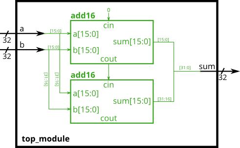
module top_module (
    input [31:0] a,
    input [31:0] b,
    output [31:0] sum
);

    wire c1,cout; //定义中间进位信号

    add16 adder1(a[15:0], b[15:0], 0, sum[15:0], c1); //实例化第一个 8 位加法器
    add16 adder2(a[31:16], b[31:16], c1, sum[31:16], cout); //实例化第二个 8 位加法器

endmodule
Problem 25 : Module fadd
module add16 ( input[15:0] a, input[15:0] b, input cin, output[15:0] sum, output cout );
module add1 ( input a, input b, input cin, output sum, output cout );
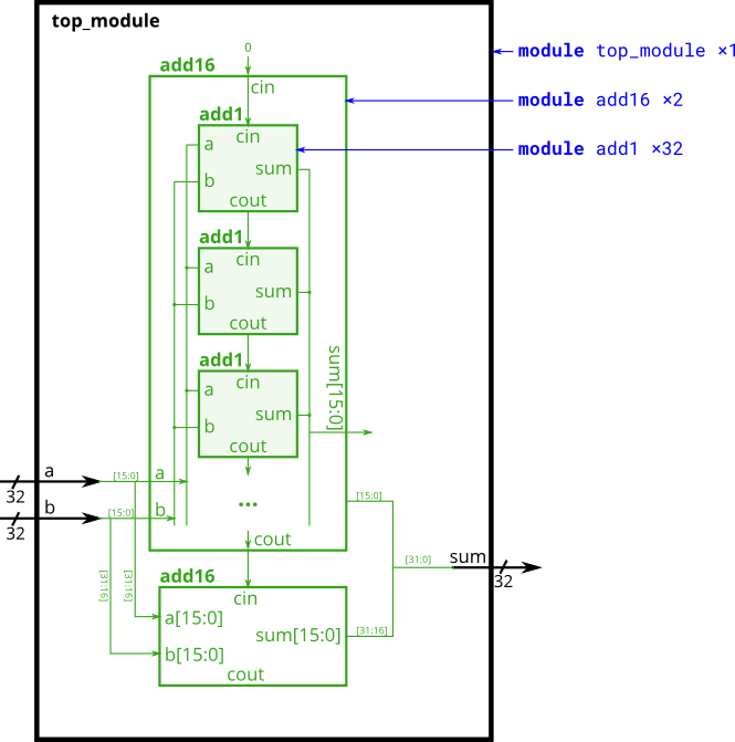
module top_module (
    input [31:0] a,
    input [31:0] b,
    output [31:0] sum
);

    wire c1,cout; //定义中间进位信号

    add16 adder1(a[15:0], b[15:0], 0, sum[15:0], c1); //实例化第一个 8 位加法器
    add16 adder2(a[31:16], b[31:16], c1, sum[31:16], cout); //实例化第二个 8 位加法器

endmodule

module add1 ( input a, input b, input cin,   output sum, output cout );

// Full adder module here
assign {cout,sum} = a+b+cin;

//全加器逻辑
//assign sum = a ^ b ^ cin;
//assign cout = a&b | a&cin | b&cin;

endmodule